Stages of the Cyclic Process
- A cyclic process is a series of transformations that takes a gas back to the original state.
- Consider the following graph, which shows the processes undergone by an ideal gas:
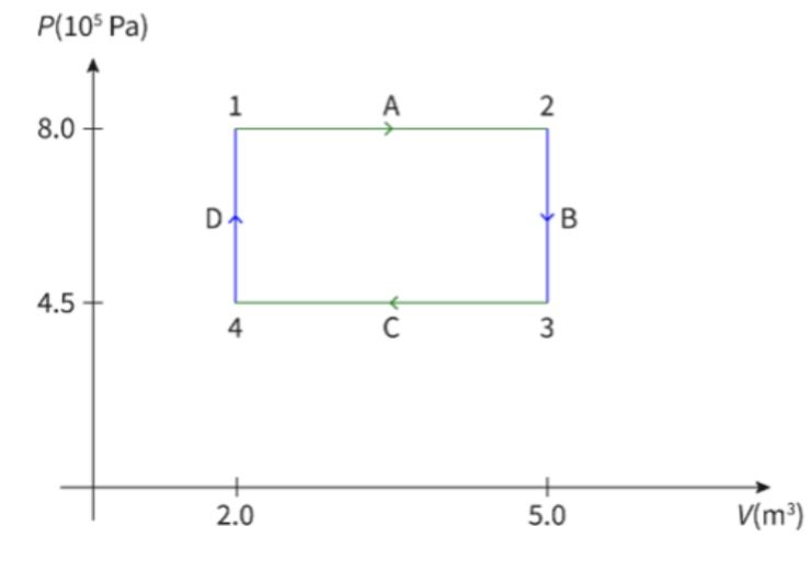
- In the A stage, the gas undergoes a isobaric process.
- Temperature and volume increase in this stage.
- Heat was added in this stage, leading to the increase in temperature and volume, as pressure was kept constant.
- In the B stage, an isovolumetric process occurs.
- Pressure and temperature decrease in this stage.
- The gas lost heat in this stage, leading to a decrease in temperature and pressure, as volume was kept constant.
- In stage C, the gas undergoes an isobaric process.
- Volume and temperature decrease in this stage.
- The gas lost heat in this stage, leading to a decrease in temperature and volume, as pressure was kept constant.
- In the D stage, an isovolumetric process occurs
- Pressure and temperature increase in this stage.
- Heat was added in this stage, leading to the increase in temperature and pressure, as volume was kept constant.
- The total change in internal energy throughout the process is 0.
- The work done is equal to the area enclosed by the cycle.
Heat Engine
- Cyclic gas processes are used to run heat engine.
- A heat engine is a device that will take energy from a hot body, and use it to do work.
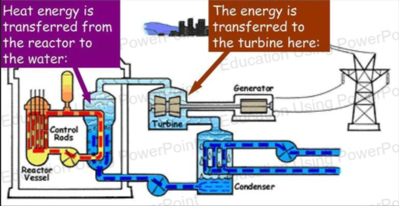
- In the above example, heat energy is transferred to the engine from the reactor, and the engine does work on the turbine to spin it.
- A heat engine can respond to different cycles and is characterized by its efficiency.
- It can be modelled using the following diagram:
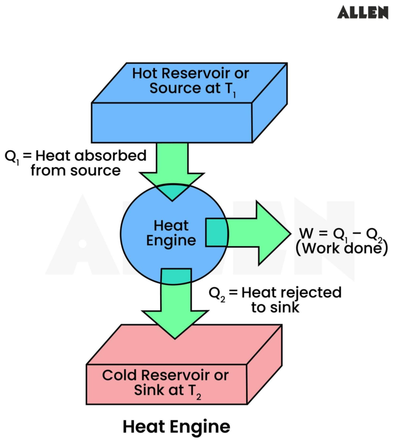
- The heat engine works in a cycle of 3 steps:
- Heat is extracted from the hot reservoir.
- For example, heat produced by burning natural gas or from a nuclear reactor.
- Some of the extracted heat is used to provide useful work done.
- For example, turning a turbine or pushing a piston.
- The unused heat is sent to a cold reservoir.
- Such as the surroundings.
- The cycle is then repeated.
- Heat is extracted from the hot reservoir.
- This model of a heat engine operates under some assumptions, such as the following:
- The heat reservoir is assumed to have an infinite heat capacity, meaning that any heat can be extracted without affecting its temperature.
- The cold reservoir is also assumed to have an infinite heat capacity, allowing any amount of heat to be added without altering its temperature
Efficiency of a Heat Engine
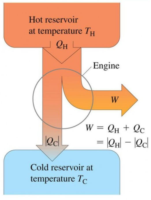
- From a previous diagram we can see that:
- Energy from hot reservoir = work done + energy given to the cold reservoir.
- Using this, and the formula for efficiency, we can calculate the efficiency of a heat engine.

- It can also be shown in a Sankey diagram.
Carnot Cycles
- Unfortunately, most heat engines are only around 20% efficient.
- A traditional heat engine heats up a gas so that it increases in volume, pushing a piston, which does work.
- Once the piston is pushed, the gas is cooled to compress it, bringing the piston back down.
- However, this is very inefficient as it requires constant reheating and cooling.
- A more efficient way to get the heat engine to do work would be to supply heat energy at the same temperature as the gas.
- The most efficient cycle possible is called a Carnot Cycle, which consists of the following steps:
- Isothermal Expansion
- Gas at temperature T1 is in a cylinder and contacting a piston and a heat reservoir.
- The gas is allowed to expand, and as it expands the gas does work on its surroundings, reducing its temperature.
- However, the heat reservoir, which is the same temperature as the gas, T1, heats it up so that the temperature of the gas stays constant.
- Thermal energy is transferred to the gas to maintain an isothermal process.
- Adiabatic Expansion
- In the second step, the heat reservoir is removed and replaced with insulation.
- As there is now no heat transfer, the gas undergoes an adiabatic process.
- As the gas expands now, the temperature reduces to T2.
- In the second step, the heat reservoir is removed and replaced with insulation.
- Isothermal Compression
- In the third step, the insulation is removed, and the gas is exposed to a cold reservoir with temperature T2.
- An external force then pushes on the piston, which would cause an increase in the temperature of the gas.
- However, increased temperature is transferred to the sink, meaning that both the gas and the sink stay at temperature T2.
- The cold sink allows this process to be isothermal as thermal energy is transferred to it.
- Adiabatic Compression
- In the last step, insulation is added back and the cold sink is removed.
- As the gas continues to be compressed, it returns to its original temperature, T1.
- In this step, there is an increase in temperature, but no thermal transfer, which shows that this an adiabatic process.
Carnot Cycle Graphs
- Carnot cycles can be shown in a graph as follows:
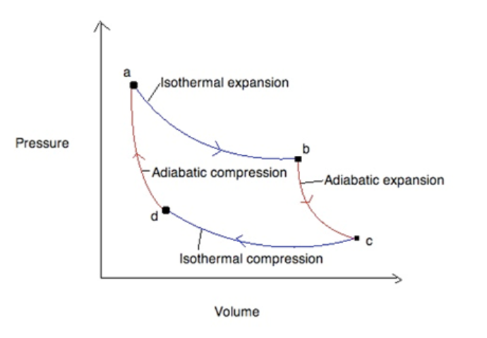
- The area encircled by the lines represents the work done during the process.
- This cycle can also be reversed, which leads to Carnot refrigeration.
Efficiency of a Carnot Engine
- The efficiency of an engine using the Carnot cycle can be given as:
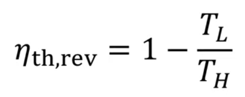
- Where TL is the temperature of the cold reservoir and TH is the temperature of the hot reservoir.
- This equation shows that the efficiency of Carnot engines is only based on absolute temperature.
- Carnot engines have the highest possible efficiency, which means a normal heat engine will always be more inefficient.
Sources
https://allen.in/jee/physics/heat-engine